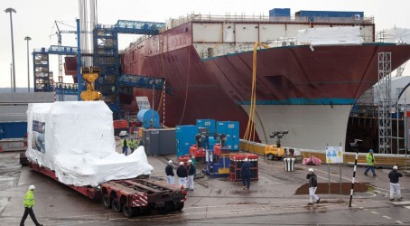
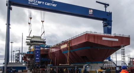
It has been a long time coming, but at last the first of the Royal Navy’s new aircraft carriers is finally starting to resemble an actual ship, with several modules fabricated around the country having been mated together at Babcock’s Rosyth yard in Scotland.
Inside the hulking structure, progress is also being made. Perhaps the most symbolic milestone was achieved when HMS Queen Elizabeth II was fitted with two Rolls-Royce gas turbines, as the ship’s integrated electric propulsion system started to take shape.
The aircraft carrier, HMS Queen Elizabeth, and a second vessel, HMS Prince of Wales, are being delivered by the Aircraft Carrier Alliance, a partnering relationship between BAE Systems, Thales UK, Babcock and the Ministry of Defence. For Jim Bennett, power and propulsion director at the Aircraft Carrier Alliance, who has worked on the project since the outset, the installation of the 36MW MT30 turbines was a seminal moment. “It was the culmination of many years of hard work,” he says. “The turbines are crucial parts of the vessel, in that they will deliver around two-thirds of the electrical power generated on board HMS Queen Elizabeth. This is British engineering at its best.”
The Rolls-Royce MT30 is a marinised version of the Trent 800 aeroengine, with around 80% parts commonality. Each QE-class carrier will be fitted with two turbines, along with four diesel generator sets giving a total installed power of around 100MW. The power generated will meet the ships’ demand for energy, which includes the propulsion motors, weapons and navigation systems, and low-voltage requirements for lighting and sockets.
“From the outset, we tried to keep as much commonality between the Trent 800 and the MT30 as we could,” says Alan Millichamp, Rolls-Royce product director – MT30. “That said, the MT30 will be operating in a marine environment, so the components needed different coatings for the salty conditions and to allow for the high sulphur content used in marine fuel.
“The engine itself has a very high thermal efficiency at just over 40%, giving 36MW, flat-rated. It also holds its power up to very high ambient temperatures of around 38ºC. Tests have shown that the engine can also be extended out to 40MW. It also has exceptional power density – it’s a 6.5-tonne component that has a very small footprint.”
Modular production of the MT30 began on the same production line as the Trent aeroengines in Rolls-Royce’s Derby factory, before the modules were assembled into the marine configuration, and put through a rigorous test and certification programme at the company’s facility in Bristol.
The turbine and associated ancillary equipment were then assembled into a steel package – the gas turbine enclosure – by Cullum Detuners of Derbyshire. Here the enclosure was joined to the large alternator, which is driven by the gas turbine to produce electrical power. After more testing, the gas turbine enclosure and the alternator were split, because of their size, and shipped to Rosyth separately. The two components were then hoisted into place using a crane.
“Mechanically integrating the gas turbine enclosure and the alternator before installation in the ship was important,” says Bennett. “We didn’t want everything coming together at Rosyth for the first time with the realisation that, for all your best CAD, there were still issues to overcome.
“Checking the removal route of the engine was another important factor – the customer wants to be able to get it in and out as quickly as possible. So, we put up some bulkheads in the exact positions that they are on the ship relative to the engine to act as a simulator. It all went fine – there were no problems.”
Together, the gas turbine enclosure and the alternator form what is known as the “gas turbine alternator” (GTA), a unit that weighs more than 120 tonnes and is 16 metres in length. The GTAs are located in sponsons under each of the ship’s two islands – in a position higher in the vessel than previous aircraft carrier designs. The removal route is via the aircraft hangar, which houses workshop space and several lifts up to the flight deck.
Having the two MT30s separated by some distance provides benefits in terms of survivability, says Bennett. The two MT30s are a long way from each other; likewise the diesel generators. The electric motors are spaced so that there are staggered shaftlines, while the propulsion motors are set across three watertight compartments, and there is subdivision within those spaces as well. That gives good survivability for flooding, he says.
“We looked at all sorts of iterations, but this was the most survivable. The HV switchboards are designed on the same principle – there is a significant distance between the forward and aft switchboards, and between them port to starboard. Spacing them out maximises survivability,” he says.
Bennett thinks that the integrated electric propulsion system is an elegant solution for the requirements of the carriers. A big driver was the immense amount of power required, and the low levels of faults expected by the Royal Navy. “These ships require a large amount of electrical power for both the propulsion and other services. The customer did not want pneumatic gas turbine starting; it was not even particularly keen on hydraulic starting. That all upped the required power levels.”
In the end, the designers and engineers on the project looked to the cruise industry for inspiration, says Bennett. “We had to go to 11kV – much like you see on large cruise ships. Modern cruise ships also have very high levels of redundancy and availability for passenger comfort, while the carrier warships wanted that for other reasons. So that led us to the same end result, looking towards the big cruise ships. Why reinvent the wheel?”
The Queen Elizabeth II is now coming together fast at Babcock’s Rosyth yard. Next step, in terms of the gas turbines, is the connecting of cables, pipes, ducting and other ancillaries. Once that is done comes the task of terminating all the related cables: a massive job, bearing in mind there are more than 3,000 kilometres of installed cable on the ship. When those terminations are made, they have to be checked, and then the Power and Propulsion Sub-Alliance, comprising Rolls-Royce, GE Energy, Thales and L3 Communications, will set it to work.
“We will then start doing our checks, building slowly, ensuring that components such as motorised valves all do exactly what we thought they would, eventually building to a point where we are ready to run our first engine,” says Bennett.
“Then we will run two GTAs together. And after that we think about the full propulsion system – decoupled from the propellers – and work through that, iteratively checking each aspect. This keeps going until we are ready for the ship’s 40-day sea trials.” Following sea trials, and once any required rectification is completed, the ship will be ready to sail.

Adapting the aeroengine for its maritime role
The Rolls-Royce MT30 used on the carriers is a marinised version of the Trent 800 aeroengine. It is a twin-spool, high-pressure ratio gas turbine that can be configured with an axial intake plenum for funnel installations, or compact rotatable radial intake for machinery space installations. It features an eight-stage, variable-geometry, intermediate-pressure compressor and a six-stage, high-pressure compressor.
The annular combustor is similar to the aero parent and designed to burn commercially available distillate fuel to DMA standard. For liquefied natural gas vessels, the MT30 would have dual-fuel capability, primarily burning boil-off gas lost from the vessel’s main gas storage tanks, but also capable of burning DMA standard fuel when gas is not available.
So what are the major differences between the MT30 and the Trent 800? Firstly, the aeroengine fan and fan casing are removed, which leaves the core of the engine. The core remains with its compressor, combustor and turbines. The shaft that in an aeroengine runs back through the centre to drive the fan, producing thrust, is removed. Instead, the shaft is reversed out of the back of the engine. The MT30 also uses a gearbox from an earlier Trent, the 500, because the Trent 800 version is too big.
Vanes inside the gas turbine that help redirect the flow of air inside the engine on an aircraft are straightened up, and anti-corrosion coatings are applied to engine components to help the MT30 withstand the rigours of the marine environment.
The engine must be contained within a compact enclosure which hosts ancillary equipment such as ventilation fans and a fire protection system.

Island installation is latest chapter as carrier comes together
The most recent major activity on the assembly of HMS Queen Elizabeth II aircraft carrier has been the lifting into place of the forward island containing the main bridge and around 100 vital mission systems compartments. The 680-tonne forward island – which arrived at Babcock’s Rosyth facility from BAE Systems in Portsmouth – was lifted into position on the ship’s flight deck by the Goliath crane, which had a special 78-tonne lifting frame attached for the purpose.
The lift process began with the attachment of the crane to the lifting frame, and application of a percentage of the island weight to the crane to confirm the predicted centre of gravity. After some minor adjustments, the crane took the full weight of the island, lifted it over the aircraft carrier flight deck and located it in its final position. Although not the heaviest lift of the project, the island’s shape presented challenges. Also demanding was the alignment of the 2.4m-diameter gas turbine exhausts, which were prefitted in the island and below in the ship superstructure.
The 22m-high by 13m-wide and 27m-long upper block 07, as the forward island is known, already has all consoles installed, as well as 43km of cables and 3,101 pipes.
With the island in place, the long range radar (LRR) will now be installed on top. This will be closely followed by a period of consolidation when the island will be welded to the superstructure and mechanical and electrical systems installed. The later phase will see the LRR set to work and integrated with ship systems.
Uniquely, the QE-class carriers will feature two islands. The second “aft island” is due to arrive and be installed by the end of July, and will operate as an airport control tower to co-ordinate aircraft movements. Both islands are designed with the ability to carry out each other’s role in an emergency.
HMS Queen Elizabeth will be structurally complete at the end of this year.

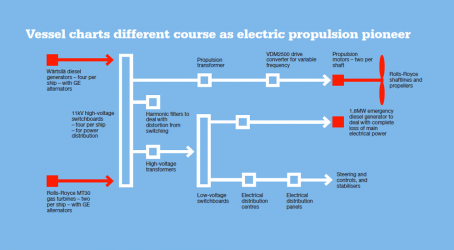
Vessel charts different course as electric propulsion pioneer
The Queen Elizabeth-Class carriers are the first Royal Navy vessels to have been designed as integrated electric propulsion vessels.
Each ship will have four high-voltage switchboards. Three of these are connected in an open ring configuration, with the forward diesel generator board connected to the forward gas turbine board only. This board is a “‘clean island” with no propulsion fed from it, but services are distributed to each of the five zones across the ship. The other major high-voltage switchboard providing ship services is the aft gas turbine board, which also supplies every zone.
Three of the high-voltage switchboards provide propulsion, with the two aft switchboards each supplying one motor. The forward gas turbine board supplies the other two.
The propulsion motors and converters, supplied by GE Energy, are as fitted to the Type 45 destroyer, with minor changes due to being transformer fed on the aircraft carriers from the 11kV system in a 24-pulse arrangement. The four propulsion motors are almost identical to the Type 45, apart from the fact that they are arranged in a “twin” arrangement with one behind the other on each shaftline. This requires double-flanged machines with larger rotor shaft diameters to transmit the through torque.
At their home port in Portsmouth, the aircraft carriers will take on shore power at 11kV, via plugs and sockets connected to the forward/aft interconnectors.