The world’s most sophisticated sea simulator is speeding up the development of marine energy devices. It calls for a complex system of drives and controls

On a land-locked site in the heart of Edinburgh, engineers have the ability to create just about any sea-state found anywhere in the world. From gently lapping waves to chaotic, raging undercurrents, they can all be produced at the touch of a few buttons.
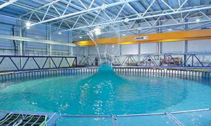
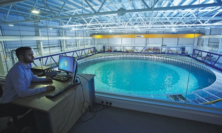
This mar-ine magic takes place at the multi-million pound FloWave Ocean Energy Research Facility at the University of Edinburgh. At the heart of the facility is a 25m-diameter circular concrete basin, 5m in depth and containing 2.4 million litres of fresh water, where 1/16th scale models of wave and tidal energy devices can be tested in a multitude of sea conditions.
The services offered at FloWave are invaluable to marine companies that need to confirm simulated performance parameters before cutting steel on larger sized prototypes. For developers of commercial arrays, meanwhile, FloWave presents an opportunity to validate micro-siting and energy yield prediction – before investing tens of millions of pounds in the project itself.
“We replicate the oceans and seas in all their complexity,” says Stuart Brown, chief executive of FloWave. “No one else can carry out this work to the sorts of accuracy that we can. Primarily the facility is used to test scale-models of wave and tidal devices, and arrays. But we have also done a lot of work on remotely operated vehicles, and are increasingly looking at floating wind turbines, which are pretty much the most complex structures that you can put in the sea. It’s ground-breaking stuff.”
The tank is ringed by 168 absorbing wave-making paddles, which can create full-spectrum multi-directional waves as well as monochromatic waves, over a circular test area of more than 200m2. Additionally, 28 submerged flow-drive units can simultaneously and independently drive current across the tank in any relative direction, moving up to 5 tonnes of water per second to create a conveyor belt of moving current above and below a raisable floor.
The flick of a switch can induce vari-directional current, allowing quick and finely tuned ebb-and-flow direction tests for arrays. Because the tank is circular and therefore non-directional, waves and currents can act in any combination and in any relative direction across the large central volume. These combined capabilities mean FloWave can lay claim to being the world’s most sophisticated sea simulator.
Optimising the design
Test conditions for currents and waves in all directions can be simply programmed and run, or chosen from a suite of standard ocean spectra correlating to actual measured sea-states. Complex wave and current conditions for normal, challenging and extreme conditions can easily be simulated and repeated. This allows devices and control algorithms to be iteratively adjusted to find optimal performance settings, and reduces the time taken to get to the optimised design.
“Certain spectra of waves represent parts of the Atlantic, and others are characteristic of the Pacific,” explains Brown. “If you have real-world data, you can reverse it, and turn it into mathematical spectra which we can use, programming it into the control system for the tank. That replicates those conditions very accurately.
“Also, because it’s then a mathematical construct, it produces a quasi-random sea. In effect, it’s not really properly random because, if there’s a particular spike of high wave at a certain moment during the test, that same spike will reoccur when we run the tank again. It’s entirely repeatable. So it looks like a random sea, but we can do it again and again.”
Under the surface, the flow drive units can physically move water past tidal devices bolted to the basin floor. Currents can be quickly and easily reversed, representing the ebb and flow of tides. “We are moving water past the devices, rather than towing devices through static water,” says Brown. “So we can replicate a tidal turbine array, flow the water at it, and then tweak it by one or two degrees left or right to replicate the changes between neaps and springs and different flow speeds.
“And we can look at it on the ebb tide with the current coming back the other way. We don’t need to change the array layout, because we are moving the water past the turbines, not the other way round.”

Parameters plotted
Collecting the data is a demanding task, says Brown. “First, we characterise the tank without anything in it, producing a map in terms of parameters like speed and turbulence, flow rates, wave conditions. We know what the tank does, and what happens when we set the controls in a certain way. Then, when we put the device in, we can measure the performance off that.
“We can also add in instrumentation, which is useful for arrays, to work out what energy is left in the resource after another device has taken out its share. Or we can put load cells on the floor of the tank and take the data off that to get the mooring bolts. Also, we have over- and under-water 3D motion capture systems to see what’s going on.”
At the heart of the facility is a package of electrical and control equipment. Servo drives and motors and variable-speed drives, supplied by ABB, are used to generate long-crested straight waves and fast currents. The computer control system combines thousands of these simple sine waves together to build a fully controllable ‘random sea’ that is 99.9% representative of real conditions. Down either side of the tank hall, marshalling cabinets house circuit breakers, contactors, relays, switches, fuses, programmable logic controllers, servo drives and variable-speed drives.
The ring of 168 wave-maker paddles that encircle the tank can create and also absorb waves. Each paddle has a brushless AC servomotor that drives a belt running over a curved guide on the top of the paddle. The brushless servomotors are used to provide the full torque from zero speed with dynamic performance, as well as avoiding the wear and replacement of brushes, thereby reducing the costs.
The velocity, position and force feedback of each paddle are controlled by a servo drive using Ethernet Powerlink. The controller takes the signals from force transducers on the back of the paddles that sense the wave-making forces. Encoders measure the paddle position and convert the signals to an algorithm that then gives instructions to the amplifiers. Ethernet Powerlink is used to give error-free, realtime control from the custom controller to the amplifiers, with protection of the latter being afforded through safe stop mechanisms.
As the paddles can both make and absorb waves, the amplifiers absorb power in the incoming wave by acting as a generator. The drive system returns the energy back into the DC bus system, rather than wasting it by dumping the energy through large resistors.
Each motion control drive is fed from a common DC bus, the DC voltage of which is generated using an ABB drive which is linked to the AC mains supply. Rather than use a conventional front end, the amplifier runs as a line regenerative supply, thereby driving the excess energy from the DC bus back into the mains system.
Twenty-eight submerged flow-drive units simultaneously and independently drive current across the tank in any direction, with maximum current velocities of up to 1.6m/s through the test volume. The current mode is ideal for testing both single devices and tidal arrays. Each 1.7m-diameter impeller is directly driven by a permanent magnet synchronous motor which in turn is speed controlled by a 46kW/60kVA industrial drive, controlled through CANopen communications via a third-party controller. Each bespoke impeller can move more than 5 tonnes of water per second.

Reduced complexity
It was important that a drive was selected that did not need any encoder feedback, so as to reduce any additional cabling or devices underwater. ABB’s direct torque control is a sensor-less motor control platform that provides the permanent magnet motors with low speed and torque accuracy, within 1% of demand, thereby recognising the rotation without any position feedback devices.
The 28 variable-speed drives are housed in electrical cabinets alongside the tank. The drives are packed in close proximity within the cabinets and, to help save space, a common busbar system is used to transfer the three-phase power to all of them. Each drive is given a different speed reference and it uses its internal logic and control systems to make the sensor-less vector motors rotate at the speed needed to generate the linear profile of current in the water.
Having so many drives rated at 46kW on a 1MW transformer generates multiple harmonics. Using diode bridges with a DC bus was not an effective option. So low harmonic versions of industrial drives with an active front end were selected to mitigate the impact of harmonics on the mains supply. The drives are fitted with safe-torque off, so if there is ever a problem within the tank, such as someone falling in, output to the motor will be cut.
The 15m-diameter hydraulic raisable floor is controlled via an integrated PLC, which also controls the filling of the tank and movement of the access and instrumentation gantry using a CANbus to Ethernet link.
This set-up means FloWave is hugely flexible in terms of the work that it can carry out. Traditionally, marine energy device development has been tested at very small scales (typically of the order of 1/67th to 1/100th scale) before jumping to a much larger scale more appropriate to sheltered real-sea conditions (for example 1/7th scale). The cost of this larger-scale work, in manufacturing, offshore deployment and testing, is considerably greater and there is an inherent risk in scaling up too quickly. This is all the more costly when things don’t quite go right at the larger scale. At 1/16th to 1/30th scale, the FloWave Ocean Energy Research Facility plugs this gap and enables engineers to de-risk their designs and so deploy ‘right first time’ in the real marine environment.
Most recently, the facility has been running trials of Albatern’s Wavenet, an offshore array-based floating energy converter designed to generate electricity in waves with heights ranging from 0.3m to 6m. FloWave has tested the device in several sea-states, enabling Albatern to confirm digital predictions with actual physical performance.
Did you know?
FloWave engineers and technicians will work with customers to guide them in the planning and preparation of their test programmes. They can also be present throughout the test period to ‘drive’ and operate the test tank.
There is also an extensively equipped workshop being developed to allow maintenance and alterations to prototype devices and scale models that are under test.
It is hoped that in the future this might be extended to offer a model-making capability for clients without the necessary expertise.